Anet A8 / AM8 SKR 1.3 Upgrade with TMC2209 and sensorless homing - Part 1 - Hardware installation
In this video, I show you how to install the SKR 1.3 mainboard with TMC2209 stepper drivers and sensorless homing into an Anet A8 or AM8.
Hello, my name is Daniel, welcome to the CrossLink channel. Our mission is to help 1 million people getting more successful with 3d printing and if you're here for the first time, subscribe and enable bell notifications so you don't miss anything.
Not long ago, I converted one of my Anet A8s into an AM8 with metal frame but if you are still on the original plastic frame, you can still do this SKR 1.3 upgrade. Technically it's the same steps except you will need a different mount for the mainboard for your frame. I've linked different mainboard mount options in the description of this video, so you have some choice.
Today, I'm going to upgrade this AM8s mainboard to a 32bit SKR 1.3 with TMC2209 stepper drivers and I'm also setting my X and Y axis to use sensorless homing, so I don't need these endstop switches anymore.
I'm going to talk about the SKR 1.4 in a future video, so you will THEN see how that installation might be different.
The main components used in this video are gonna be:
A 3D printed mounting frame for the electronics
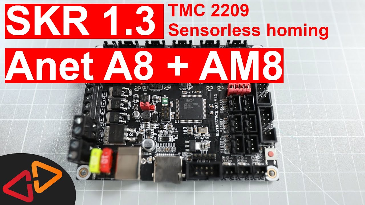
The SKR 1.3 mainboard
A raspberry Pi with Octoprint - this is of course optional and can be added later
two MosFets for the Heatbed and Hotend - I would recommend at least to use a MosFET for the heatbed. I am using also a MosFET for the Hotend.
At least four TMC 2209 stepper drivers
A 120mm Fan for cooling the electronics, mounted on another 3D printed frame that gets attached on top of the electronics mounting frame
This fan is a 12V fan and since my frame runs on 24V I am also using a buck converter to regulate the voltage for that fan down to 12V or less.
The Mainboard Fan is mounted to another frame that slides on top of the electronics holder
Let's walk through the installation step by step.
First of course, I need to remove the existing electronics holder from the AM8. So I remove all the connections first and then disassemble everything attached to the frame.
Then, I take the new electronics frame and fixed the two MOSFETs to it. These need to be mounted before the mainboard, it's more convenient to reach the counter-nuts from the backside.
Now, Let's have a look at the SKR 1.3 mainboard. The first thing, I made sure is that this red jumper in the middle of the board is set to internal power, not to power from USB.
I am using a Raspberry Pi later to connect to the mainboard and I don't want to power the SKR mainboard from the Raspberry Pi, which otherwise could cause an undervoltage issue at the Raspberry Pi.
Here at the top, we have the sockets for the stepper drivers and there is four jumpers in each socket to configure the stepper drivers connection modes. I am first removing all jumpers from the stepper driver sockets to start from scratch.
And then, I am also removing these 5 RED jumpers here on the right hand side, which configure sensorless homing for each driver. Sensorless homing is a feature that is supported by the TMC2209 stepper drivers but there is also other models that support this like the TMC 2130 for example.
I am configuring the TMC2209 stepper drivers to run in UART mode for this, so I have to install the correct jumpers here right below the sockets. There is a red marked jumper slot for every stepper driver that needs to be set if you like to use UART mode on it. I'm doing this for all four stepper drivers that I'm using in this build.
And then, to enable sensorless homing for the X and Y axis, I need to install two jumpers to the most left jumper connectors here, where we removed the other five jumpers in the beginning.
All jumpers are set - It's time to install the stepper drivers. Make sure you orient them in the right way, the Ground pin, labeled with GND needs to be top right. In the case of the TMC2209, the potentiometer will be on the left hand side.
And now, carefully push the stepper driver into it's slot. I'm doing this for the other ones in the exact same way.
And because stepper drivers emit quite some heat and so need to be cooled, I am also installing the provided heatsinks on top of each stepper driver.
Now, I have a fifth stepper driver slot left, that I could use to drive the second Z-Axis motor from a seperate stepper driver.
But I am choosing to use a parallel connection adapter, that has one input plug and two output plugs, so I can run my Z-Axis motors from one stepper driver.
And now - it's time to mount the SKR mainboard to the mainboard frame.
On the backside there is still plenty of room for an optional Raspberry Pi. I am going to install it to run Octoprint from it and a camera to monitor my prints.
So this electronics frame looks great, very clean and read to be installed to the AM8.
The installation is rather simple, I only need three screws and three T-Nuts, which fit into the metal frame slots, then just a few turns with the hex-wrench and it's fixed.
And though it looks like the electronics on the back extend into the build area, there is actually enough space left to fit a hand in between.
Finally, the frame needs a little more fixing on the other side, so it wobbles less. Therefore I used only one additional screw and t-nut, which is absolutely enough to make it really sturdy.
Next, I am installing the power cables, starting with the MOSTFETs, which have a seperate power cable coming from the Power supply. With a another pair of cables, I am distributing power to the second MOSFET.
Then, I connect the hotend power cables to the upper MOSFET and the heatbed power cables to the lower MOSFET.
The mainboard on the other side has it's own power cables coming from the power supply.
Now, I'm starting to install the stepper motor cables. First I'm connecting the Y-Axis duplicator and then connecting the Y-Axis motors to it. Then the X and Y motors follow, as well as the Extruder motor.
I had to exchange the old three pin plugs for the hotend and heatbed temperature sensors with dupont connectors because the SKR 1.3 only has two pin connectors for those.
There is three connectors on the SKR 1.3 for temperature sensors here in the lower right corner of the mainboard. I connect the heatbed sensor to the right plug and the hotend sensor to the middle one.
I am not using the X and Y endstop switches anymore, so they are left unconnected.
The Z-Endstop switch however, still needs to be connected. In this video, I am going to use the original switch that came with the Anet A8. If you like to know how to connect other probes like these, including the BLTouch to the SKR 1.3, watch out for another video that I'm going to do just covering these sensors in a bit.
You will need to modify the the Existing Anet A8 endstop plug to work with the SKR 1.3. Originally, the cables are on the 1st and 3rd pin and for the SKR 1.3 we need to change the pins to be on the 1st and middle pin.
Now what I consider to be the first pin is when you put the plug to the table with the metal connector pins facing up, the first pin is on the left.
You can push down the lock of the pin with pliers and then pull out the pin and push it back into the new slot.
So let's plug that in into the Z-Endstop slot, which is the lower left one of this group of six endstop slots on the SKR 1.3.
Now we connect the hotend and parts cooling fans but there is another change that you need to make to these before doing that.
The existing connectors can be re-used but you will have to swap the plus and minus cables, same method way as I've shown you for the endstop switch - otherwise the fans won't turn.
Again, looking down on the plug with the metal connectors facing up, the black minus cable needs to be right and the red plus cable needs to be left.
After doing that, the hotend cooling fan, that's the one that is permanently running, is going to this slot left of the first stepper motor connector.
The parts cooling fan is going to be plugged into the slot that sits below the first stepper driver.
What's left? Yes, I still have to connect my Display. I'm going to re-use the Anet Full Graphics display, I already installed in one of my previous videos and in another future video, I will show you how to upgrade to the Bigtreetech Color Touch Display on the SKR mainboards.
However, we cannot just plug the existing display cables in like they are. There is some modifications to be done, which are also explained in detail in a guide I found on Thingiverse. I've put that link in the description for your reference.
The guide shows, that you need to remove the nose of the LCD connector so you can insert it reversed into the EXP1 connector on the SKR mainboard and additionally, you need to swap the plus and minus pins, so pin one and two and also pin 9 needs to be connected to the cable of pin 7, while pin 7 is actually left unused.
As I said, the detailed explanation is in the guide, this might be the most difficult modification you need to make to get this build done using this kind of display. But with a little soldering and some shrinktube, I think it can be done in a really clean way.
So that modified plug goes into the EXP1 connector reversed, so the red cable is on top. Finally, accoring to the guide, from the J3 connector on the display, I am just using PIN 7 and I'm connecting that to PIN 3 on the EXP2 connector of the SKR using a jumper wire.
That should be it regarding the Display connection
Now, I'm mounting the mainboard cooling fan and connect it to the same plugs where the power connectors connect to the mainboard - done!
So, the electronics installation is complete for today. In the next video, I'll talk in depth about how I configured the Marlin 2.0 firmware for the SKR 1.3.
I've also linked some other videos for you in these two cards here and here.
Hope to see you soon on this channel, See you next time!