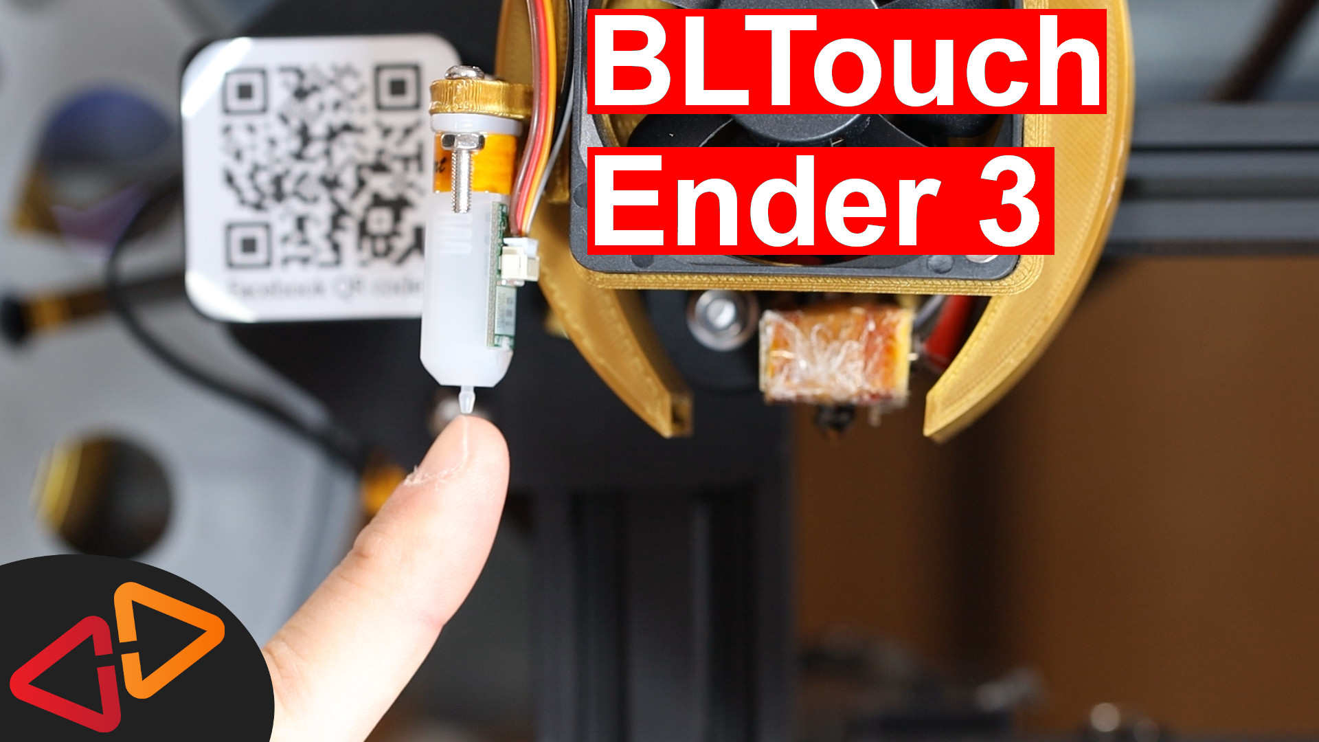
In this guide, I am installing a BLTouch sensor on this Ender 3 using the stock Creality mainboard and Marlin 2.0 firmware.
Hello, my name is Daniel, welcome to the CrossLink channel. Our mission is to help 1 million people getting more successful with 3d printing and if you're here for the first time, subscribe and enable bell notifications so you don't miss anything.
Ok, first of all, let's ask ourselves the question, why would the Ender 3, an Ender 5 or CR10 need a BLTouch sensor - at all?
Honestly, for 90% of you, it's not a must have feature. This Ender 3 works awesome since over 16 months, printing hundreds and hundreds of hours without ANY bed adhesion issues.
So why do I still install a BLTouch? Well, I intend to switch around the bed surfaces a bit. Trying out different print surfaces like the original Creality coated glass surface, metal sheets, magnetic surfaces and more stuff.
So I am not eager to do a new bed leveling all the time when I switch out the build surface. That's where I am hoping that the BLTouch will help me to be more efficient and still get consistent results.
As every time, all the links to documentation, files and the parts that i'm using are in the description of this video.
A few words before you start because I think this is a common mistake that people make when they implement any kind of bed leveling sensor. Make sure that your printer bed is actually leveled correctly in the corners. So really take your time, level the corners so they are equally distanced from the nozzle and then start implementing auto bed leveling. Your print results will be much better and doing the fine tuning with auto bed leveling will be much easier if you do this upfront.
So let's talk about the prerequisites for this modification.
You will need a PIN27 adapter that I've shown already in another video. So make sure this in place. I've also linked this in the description.
You will also need to have your PC ready to compile Marlin firmware. I'm using a fresh copy of Marlin 2.0.5.4 and the 2.0.5 configuration files for the Ender 3.
So in case you never did this before, make sure, you check out the other videos about Marlin 2.0 on my channel.
The other thing you will need is a mounting bracket for the sensor on your printer. And there is a lot of different mounts available depending if you have a rather unmodified printer or a heavily modified one like this one.
I've linked several different mounts for different scenarios in the description of this video.
To mount the BLTouch to MY Ender 3, I had to remix an existing mount.
So, I've swapped out the old version with the new version.
here at the side of the fan duct you can see, there is a new place to mount the bltouch holder with two m4 screws.
Quick tip, if you find that your screws don't fit in on the first try, heat up the part a little bit with a heat gun and then pre-tap the screw holes.
The BLTouch on the other hand gets mounted to this holder using two m3 screws and nuts.
My sensor is an original BLTouch Smart version 3.0 from Antclabs. I also have the 3D Touch here, which is a cheaper clone, that should also work with this setup. Basically, all the clones work similar. There might be some differences in the Marlin configuration, but we'll talk about that later.
Because some of you mentioned that different versions of the bltouch and 3d touch come with different cable colors, I would suggest you note down the cable color assignment at the back of the sensor so you know, which cable is connected to which pin at the bltouch.
The most important thing is that the BLTouch sensor needs to be mounted at a very specific height above the nozzle. Looking at the original Instruction manual from antclabs, the height difference between the nozzle tip and the bltouch tip when it's retracted can be between 2.3 and 4.3mm. So if we add those 4.3mm to the 4mm that the tip will about stand out from the housing, the bltouch housing's lower end should be 8.3mm away from the printbed.
So, the best way to check this is to print a leveling tool, which is going to help to check and adjust the height of the bltouch probe vs. the printbed.
So, how is the leveling tool used? First, you bring down the nozzle to the printbed. If you can still auto-home on your printer, use the auto home function for that. That's why I said in the beginning, leave it in place and connected, it might be useful later.
The alternative is to bring down the nozzle manually by turning the z-lead screw until the nozzle touches the bed and you might wanna put a piece of paper in between nozzle and bed because that is the distance, we're going for later in the final calibration.
Then, pushing the leveling tool underneath the bltouch should leave no gap. it should touch the bltouch housing and sit there quite firmly.
Next, let's make sure we get our cables sorted out correctly. With the BLTouch, normally there come some extension cables, but if not, you can also use some ordinary servo extension cables like these. You really need them because as like the other cables, you need to route these cables the same way back to the mainboard and that might be quite a long distance like in this case.
Since these servo extensions look identical, I am marking the other ends to remember which cable was connected to which one at the bltouch.
Next, we connect the BLTouch to the creality mainboard.
Here on the mainboard, we have two connections to do.
First, we connect the two endstop pins with to the Z-Endstop slot. So, now it's time to unplug the old endstop switch.
As I am using a three pin servo extension, I am replacing the connector with single dupont connectors, but if you are lucky to get extension cables with your bltouch, you probably don't need to do this.
Then, insert the two pin connector so the black cable is connected to the left pin and the white cable - in my case because of the servo extension, it's red - is connected to the right pin of the Z-Endstop slot. I consider right to be the side where the SD card reader is located.
Now we have three cables left to connect, that's the sensor pins. So double check the pinout of the BLTouch or 3DTouch version that you have noted and connect the signal pin, 5v and gnd pin to the corresponding pins on the PIN27 adapter.
Plug the display cable back in and then the PIN27 into the display connector slot on the mainboard.
You can also remove the old Z-Endstop switch from the frame, it's obsolete now.
So, hardwarewise, the BLTouch is installed and when you power on the printer, the BLTouch should at least make it's little up and down check. This will also tell you that the power is connected correctly.
Let's move on to the Marlin 2.0 configuration. And for this, I am using Visual Studio Code with the PlatformIO and Auto Build Marlin Extensions as in all of my previous videos about Marlin 2.0. I've linked a guide up here, where I expain the setup of the build environment just in case.
Also be aware that the line numbers I am mentioning might change over time as lines get added or removed to the configuration files, so using the search function to find the options might be better.
So, In Configuration.h, we need to find the BLTOUCH option, which is here at about line 891. Enable that to tell Marlin, we are using this specific kind of probe.
Next, starting at around line 944, there is a section, which is really important and totally confusing for a lot of you and I can relate because the way how it is written here and described can be sometimes misleading.
So what we want to fill in in the end is this NOZZLE TO PROBE OFFSET
So let's assume the nozzle is here, THIS is the front of the printer, THIS is the back of the printer.
Any position of the probe behind and/or to the right of the nozzle, is going to be positive values.
Any position of the probe to the left or to the front of the nozzle is considered to be a negative value.
So what you need to measure now is how much distance is there between the nozzle and the probe in each direction.
So in my setup, the probe is to the front and to the left, so the values are going to be negative in both cases.
And the amount of distance is 35 mm to the front and 49 mm to the left.
So my final NOZZLE TO PROBE OFFSET is going to be -49 comma -35 comma zero.
The third value is for a Z offset, which I'm going to ignore for now.
And don't enter it in the sample here but in the actual config line here below and don't ask why I'm saying this.
then there is MIN_PROBE_EDGE around line 967, a setting that defines how far away from the bed corners, the probing grid is going to be. Default is 10mm, which is fine for most cases but if you're using the bed clamps and such a huge fan duct like me, probably increase that to 20.
MULTIPLE_PROBING here at about line 987 defines, how often the sensor will measure the distance per probing point. So, normally, the probe takes one distance measurement per point and then moves on to the next point. If you discover that the results have a lot of variance, doing more probes per point can improve the accuracy but will also increase the time needed for bed leveling. I'm leaving it commented out for now.
Then, look for MIN SOFTWARE ENDSTOP Z, that should be around line 1124 and comment it out. This makes sure, we can calibrate the probe offset later correctly.
In about line 659 make sure, Z MIN PROBE ENDSTOP INVERTING is set to to true
and also check that Z MIN PROBE USES Z MIN ENDSTOP PIN in line 835 is enabled.
Next, we'lll go to about line 1209.
Here we find all the main switches to turn on different bed leveling options. So whatever is currently configured here for your printer, the only one we're going to enable for this tutorial is AUTO BED LEVELING BILINEAR. Every other option here should be disabled.
There's a fairly sophisticated option here, which is called Unified Bed Leveling. We'll touch that in another video for sure, but if you're just starting out, the bilinear bed leveling is totally good enough and much simpler to use.
Next, I am making sure that RESTORE LEVELING AFTER G28 is off, that's around line 1219, because that might have been enabled if I had MESH BED LEVELING enabled before. So if you are coming from that kind of setup, make sure it's commented out for this tutorial.
Let's move on to this section here around line 1232, where we wanna make sure ENABLE LEVELING FADE HEIGHT is enabled. Leveling fade height is a value that determines at what print height, the firmware starts gradually to remove the leveling corrections and that height can be configured later or it can also be disabled, so it will correct levels for the whole print, but normally above something like 10mm, leveling corrections are not necessary anymore, they basically have no effect anymore. So we wanna make sure we have the option to fade out the bed leveling if we want to.
Ok, next, there is a section with more settings for the auto bed leveling here at line 1258. The GRID MAX POINTS setting defines how many probe points the software will do in the x and y dimensions. This is normally set to 3, means we get 3 by 3 points, resulting in a total of 9 probing points. If you increase that number, I would actually make sure that it is always an uneven number so the middle point is always probed for, otherwise if we do 4 by 4 for example, there will be no probing point in the very center.
Also keep in mind that increasing that to a higher value will also increase the amount of time needed for the auto bed leveling process before your print will start. So anything beyond a 5 by 5 grid is probably not very useful but that's also individual for your kind of printbed. A glass pane might need less probing points than a metal sheet for example because the assumption is that the glass pane is more even and not so bumpy.
EXTRAPOLATE BEYOND GRID is another useful feature to enable. Let's assume that your bed is tilted and this is a very overexaggerated sketch. But let's say you only probe for these points here seen from the side and the tilt is not extrapolated to the outside, the assumption of the software would be that your bed looks like this. So let's just enable it, so it extrapolates that assumed tilt also for these outer points, just in case you like to print something really large.
Then, around line 1318, enable LCD BED LEVELING. This wil add a menu option for the printer menu to actually use and configure auto bed leveling from the printer menu, otherwise you only can use GCODE commands to configure anything.
Next, we need to enable Z_SAFE_HOMING at line 1363. This will make sure that running a G28 Homing command or an Auto Home from the printer menu will do this in the center of the bed. Otherwise, the sensor might be put in a position outside of the bed and so it will have nothing to trigger and run the carriage into the frame or the nozzle into the bed.
OK, that's all the changes for Configuration.h, let's move on to Configuration_adv.h.
We'll do some BLTouch settings here at around line 606 and below.
The first one is BLTOUCH_DELAY, which you might want to enable and set to 500, this will make sending commands to the probe a bit more reliable.
Then, for most DIY printers where you have open electronics and unshielded wires, it could make sense to enable BLTOUCH FORCE SW MODE if you find that the probing is unreliable. but let's keep it disabled for now.
In the comments of these settings there is sometimes mentioned whether the setting is meant to be for a specific version of the BLTouch sensor or if it should also work with clones like the 3D touch but there is also some settings here that are specifically only for the BLTouch v3.0 and 3.1. If you're not 100% sure that you have any of those, leave these settings untouched.
There is a so called 5 volt mode for the BLTouch smart version 3.0 and 3.1, which is supposed to create more reliable results or more precise measuring but I have to find out if that is really the case. It seems this is enabled by default on the Ender 3 configuration, so I am going to leave it as it is.
Finally, we need to make two changes to reduce the size of the firmware so it fits on the mainboard.
In Configuration.h enable SLIM_LCD_MENUS around line 1688.
and in Configuration_adv.h disable ARC_SUPPORT in around line 1629.
Good, let's compile the firmware and upload it to the board. If you missed my my video on how to do that for the Ender 3, I've linked it up here for your reference.
If you run into another EEPROM error like me, you need to load the default configuration using the configuration menu and then the restore defaults item, followed by a stored settings and finally recycle power once again, so the error will disappear.
So, the new firmware is installed on the printer, let's start by doing an auto home to see what's going to happen with the BLTouch installed.
The new thing you notice is that the printer does the z-homing with the probe in the middle of the bed. If you see that the homing is done with the nozzle in the middle of the bed, you probably have not set your Nozzle to probe offset correctly.
If you fix that, you also need to restore the default settings and store them again, otherwise the new nozzle to probe offset will not have any effect.
What we should do now is to calibrate the z-offset, that's setting how close we like to have the nozzle to the printbed when it is at zero height.
First, heat up the nozzle and bed to your normal printing temperature, for me that's 215 for the nozzle and 60 for the bed.
Then, do an auto home again.
Now, let's bring down the nozzle to the printbed using the Motion - Move Axis - Move Z Menu. I am using 0.1mm steps and will move the nozzle down until it touches the paper sheet and I can feel some resistance.
So, you wanna note this new negative probe offset, in my case -0.4.
Now, go to the configuration - Probe Z Offset menu and set this value to the probe offset, so I am going to set it to -0.4.
Then, in the configuration menu, use the store settings item to store that new offset into the EEPROM.
And we'll do another auto home.
So, the new starting Z-Offset after the auto home will be 10.04, which is the original offset + the absolute value of the offset.
If you now bring down the nozzle again to 0.0, it should be exactly at the desired distance where it grabs the paper. If not, change the z-offset setting accordingly and repeat this test.
Next, I wanna do a final check if the Auto Bed Leveling command does what it should.
So let's send the printer a G29 command or we can also invoke the Level Bed function from the Motion - Bed Leveling - Level Bed Item to start a bed leveling.
The printer now probes in the 9 points, I have configured in the firmware.
Finally, what you need to do is to enable bed leveling in the start GCode of your slicer software by adding the G29 command in a new line after the G28 command.
Now, you should be ready to use auto bed leveling in every print.
I hope you find this video helpful, if so, give it a thumbs up and also watch some of my other videos, I've linked in these two cards here.
See you next time, bye bye!
Hi Daniel. I’ve found your videos excellent and have now become a Patreon supporter. Keep up the fab work!
I have a question I am hoping you can comment on for me and others. I have an ender3 pro and added a BL touch successfully. More recently I installed an SKR mini E3 V2 board. All good. However, I worry that I don’t have any physical protection to stop the carriage crashing into the bed. I did this the other day when checking my z probe offset – I was moving the z axis and accidentally selected 10mm steps instead of 1 min steps. It was horrific and by the time I leapt for the power switch the x carriage arm was at a nasty angle! I have my BL touch connected to the 5pin port on the SKR which means the z stop pins on the board are free. Is it possible to wire back up ,y z stop microswitch as a safeguard to stop the z stepper? I looked in Marlin but really wasn’t sure what the right settings would be. Do you know if Marlin supports what I am proposing? Many thanks.