In this guide, I'll show you how to do a serial port pin breakout on your Creality mainboard.
Hello, my name is Daniel, welcome to the CrossLink channel. Our mission is to help 1 million people getting more successful with 3d printing and if you're here for the first time, subscribe and enable bell notifications so you don't miss anything.
"This hack is probably something you will never do"
This might be one of the most rarely done hack to the Creality mainboard - breaking out the serial connection pins.
Why would you do that?
For my part, I like to connect an ESP32 to this mainboard over a serial connection and run ESP3D on the ESP32. So in the end I hope to get a wifi enabled Ender 3. But if you happen to have a broken USB chip on your mainboard, using an external USB adapter instead could alse be a reason to use this hack.
The Creality mainboard has a USB port, which is connected to a USB to serial chip that makes it possible to connect this mainboard to a PC and use the USB cable as the serial connection.
We will hijack the RX and TX pins, that are building the serial connection to break them out to two seperate cables. Then we can connect those to an ESP32 later to operate the printer over the serial connection.
What this also means, is that at no time, the USB connection can be used at the same time as another device uses the RX and TX pins directly.
Let's have a look at the mainboard, where we can hijack those RX and TX pins.
At the back of the mainboard, a bit southeast of the stepper driver heatsinks, there is two little holes, which route the RX and TX wires from the front of the board to the back.
Looking a bit closer we also see that these pins are very tight together, but I am going to try it anyways.
First step is to scrape off the soldering mask from the two connector holes. I am using a scalpel to do this. To be honest this is one of the main reasons to have a magnifying glass.
Also I'm very careful not to damage any surrounding connections. Partially, I scratched off the coating of a nearby connection a little bit, I hope this isn't going to cause an issue later.
So this looks at least useable for a first try to solder cables on.
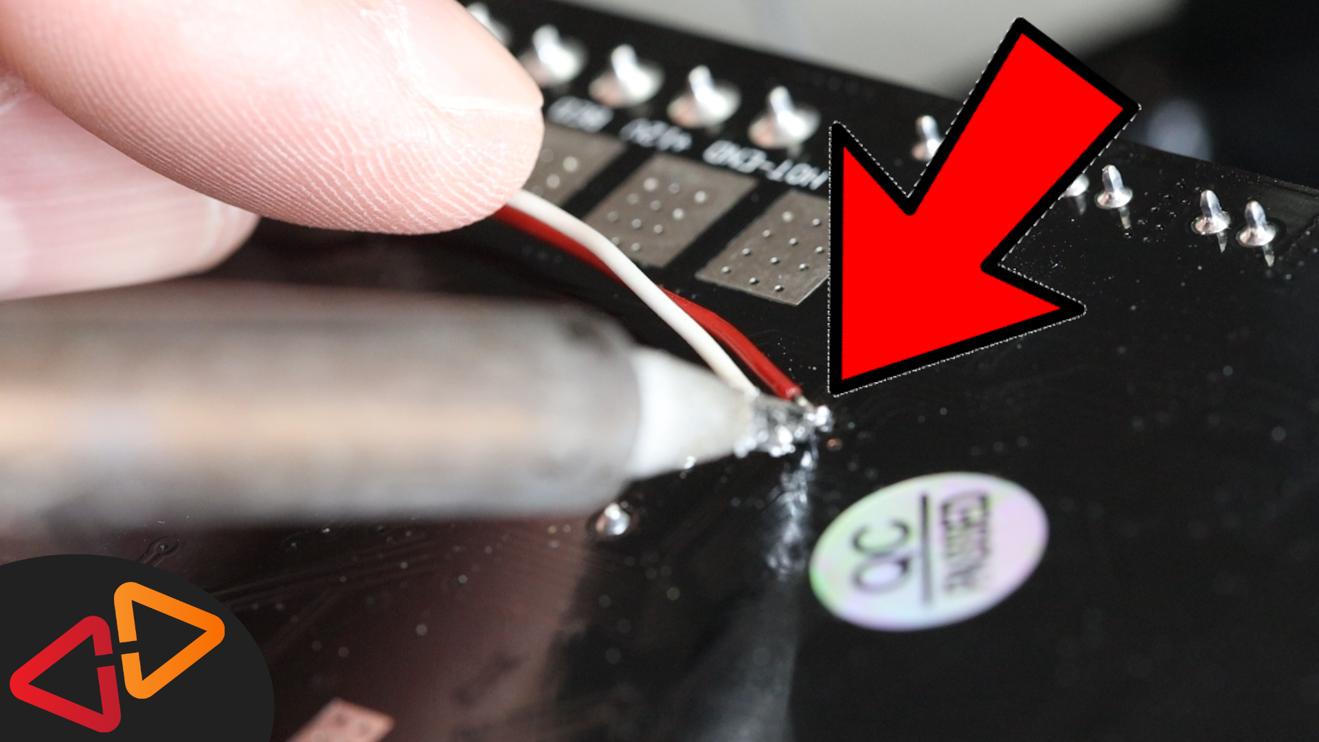
I've pre-tinned the wire ends a bit so I just have to heat them up once I hold them against the connector hole.
This was by far the hardest part, because I got a little nervous here but it turned out to be holding up well enough.
But I saw that moving around these wires could break the connection because it is such a tiny area to connect to, so I taped down the wires to hold them in place.
After reinstalling the mainboard in the electronics case, I needed to steal a ground pin from the mainboard. There is one at the ICSP connector next to the display connector.
So now it's time to test whether this alternative serial port breakout works. For that I am using a serial to usb adapter, which is a super cheap component and useful for tinkering with any arduino board as well.
This adapter gets connected to the gound pin and also to the rx and tx pins from the mainboard.
So let's connect the adapter to the computer and try to use pronterface to connect to the printer.
Ok, my first attempt was not succesful, I am going to swap the rx and tx cables, probably confused them.
Let's try again.
And we have a connection.
Looks quite normal. Let's send some commands like an auto home.
Ok, that seems to work fine.
So you've seen the serial port breakout is a little challenging for your soldering skills but it's useful for later projects or if you need to fix a broken USB chip on the mainboard by replacing it with an external module.
Next up I will use this connection for my ESP3D experiments, so stay tuned for more videos.
I hope you liked this one and if you're interested I've linked two other videos here in these two cards.
See you in the next one - Bye!